Home Resources CS025 Multi Seal Integrity
Case study
Locating the source of B-annulus pressure enables operator to restore the production of multiple wells
Multi Seal Integrity Resource ID: CS025

Challenge

In India, approximately $1.2 billion is lost per day due to well integrity issues. A major operator performed a gas lift on a newly drilled well to initiate production but when the sustained annulus pressures (SAP) raised to alarming levels in nearby well systems, all wells had to be shut in resulting in a loss of production from multiple wells. The scope was to identify the path of communication between the inner and middle annulus of the subject well.

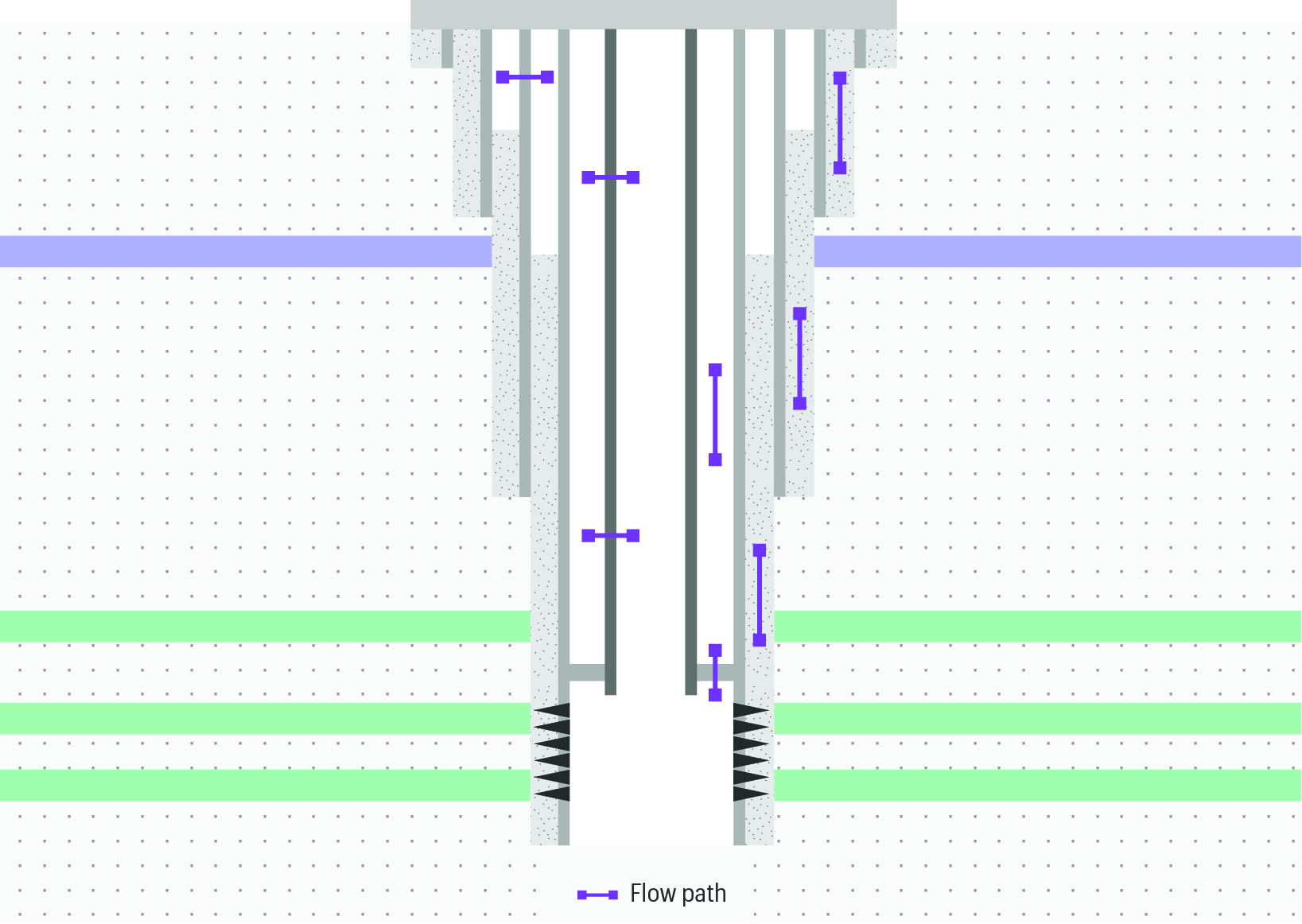
Multi-Seal-Integrity-well-sketch
Multi Seal evaluates the seal performance of multiple barriers, locating leaks and flowpaths throughout the well system, from the wellbore to the outer annuli.

Solution

The client requested Multi Seal Integrity product, which provides a clear and complete diagnostics of leaks and flowpaths throughout the entire well system. Multi Seal Integrity is delivered by the True Integrity diagnostic system and uses the Chorus acoustic platform with thermal measurements from the Indigo platform, to identify flow through multiple barriers, even at low build-up leak rates.


A diagnostic programme was designed to capture a baseline fingerprint during shut in conditions. This was then followed by fluid injection into the inner annulus while keeping middle annulus venting. The approach meant a continuous circulation was achieved, providing clear evidence of well system seal failures.

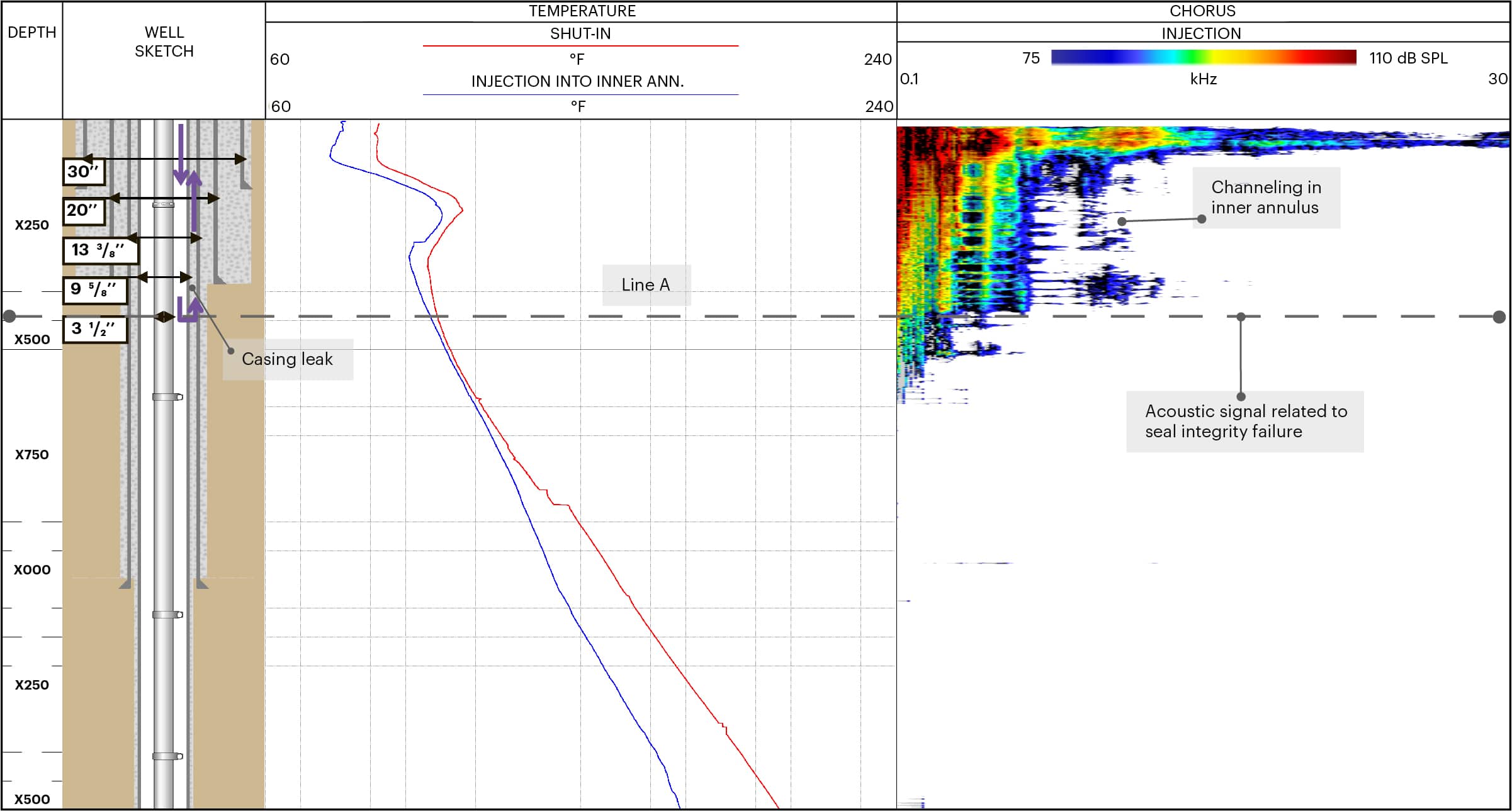
CS025-Multi-Seal-Integrity-Logplot
During the injection into the inner annulus with middle annulus venting, a strong acoustic signal can be seen in Line A– which can be attributed to a casing leak. The frequency of this signal indicates that there is fluid movement up to surface through a channel in cement.

Result

The diagnostic results revealed specific acoustic signals under fluid injection into the inner annulus (See logplot). The acoustic signals can be associated with seal failures in the 9⅝” in casing, depicted by Line A.


Acoustic signals with maximum amplitude at low-frequency extended from the leak point (Line A) up to the surface indicates the fluid movement through a channel in the cement behind the 9⅝” in casing. Based on the diagnosis, the operator was able to design a cost-effective remediation plan with an optimised and targeted workover.


Thanks to the accurate Multi Seal Integrity results, the workover was a success and the well was handed over to the production team in good working order. The asset team were then able to successfully use gas-lift techniques to optimise production, without any negative consequences to nearby well systems.