Home Resources CS019 Fibre Flow
Case study
Unlocking fibre data defines flow profiles in complex, commingled injection setup
Fibre Flow Resource ID: CS019

Challenge

In commingled injection schemes, it is essential to determine the distribution of injection rates among the different layers. This is traditionally achieved using conventional production logging surveys. Cost is also an issue, as operators have to cover the costs of the survey and the mobilisation of crew and equipment to the wellsite. In addition, conventional surveys have a small associated health, safety and environment risk because production logging tools have to be run inside the wellbore during active injection. Consequently, the industry is always seeking accurate and cost-effective injection profiling methods that reduce health, safety and environmental risks and utilise existing resources.

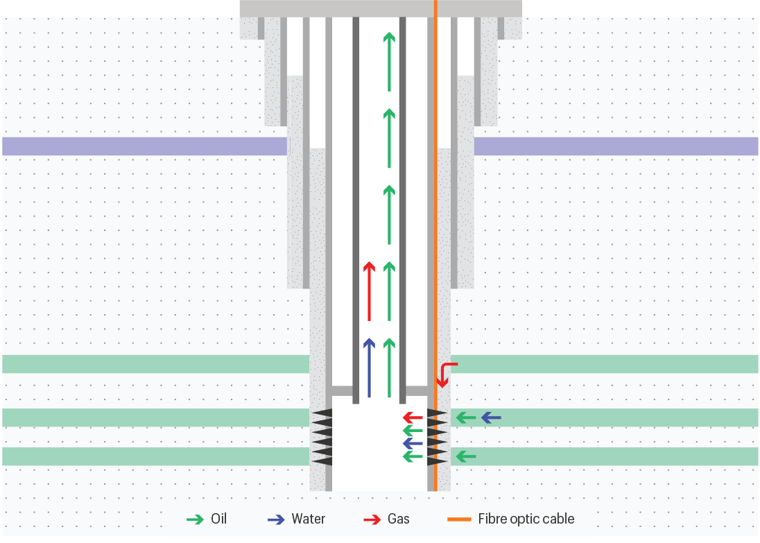
CS019 Fibre Flow_Well sketch
Fibre Flow is commonly used to diagnose unexpected or undesirable well system behaviour, but it can also be used proactively to ensure the well system is working optimally.

Solution

Flow profiles can be determined by interpreting temperature data acquired from a permanently installed downhole fibre-optic cable but, until now, accuracy has been a limiting factor. This technique, referred to as distributed temperature sensing (DTS), is an effective alternative to conventional production logging methods. After initial installation, permanently installed DTS systems have no associated mobilisation costs and eliminate the risks of well interventions.


The well in this example is a vertical water injector in the Middle East. It was drilled and completed as a cased-hole perforated injector and had an optical fibre permanently installed on the outside of the casing. Water is injected into three sandstone layers, each with different permeabilities, that are interbedded with shale units. Petroleum Development Oman selected TGT’s Fibre Flow product to quantify the flow profiles in the well system through temperature modelling of DTS data. Fibre Flow is delivered by the True Flow diagnostic system using Cascade flow modelling technology.

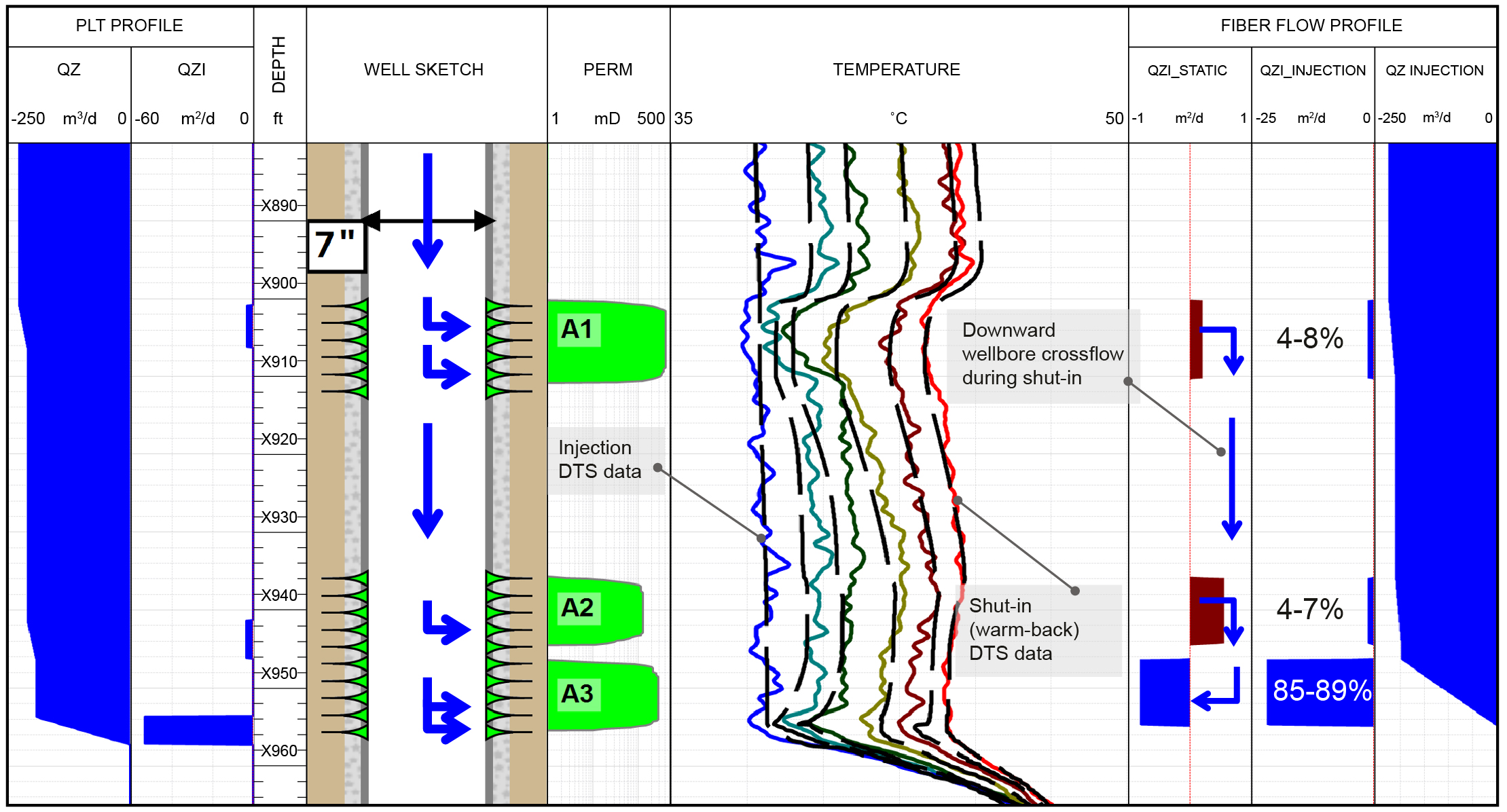
CS019 Fibre Flow_Logplot
TGT’s Fibre Flow product revealed that most of the injected water entered the bottom zone (A3) and identified a downward crossflow from A1 and A2 into A3 under shut-in conditions.

Result

TGT’s Fibre Flow product delivered accurate, quantified injection rates for three different zones (A1, A2 and A3) in the subject well.  It also revealed the presence of downward wellbore crossflow under shut-in from zones A1 and A2 into A3. The crossflow was identified by studying the ‘warm-back’ effect in the DTS shut-in temperature as it shifted towards the average near-wellbore temperature. The Fibre Flow results were seen to be in good agreement with a conventional production logging survey that had previously been run in the well.


Fibre Flow has the potential to unlock the value of fibre-optic systems that are already installed in thousands of wells. Using existing built-in monitoring systems means the operator is maximising available resources and installation investment. Also, avoiding an intervention significantly reduces the carbon-footprint of the survey. In this case, Fibre Flow helped the operator to make better use of the fibre-optic systems already installed in the well and enabled it to assess important well performance criteria, including validating correct water injection.