Home Resources CS027 Multi Seal Integrity
Case study
Diagnostics locate casing leak and help operator avoid costly workover to restore well
Multi Seal Integrity Resource ID: CS027

Challenge

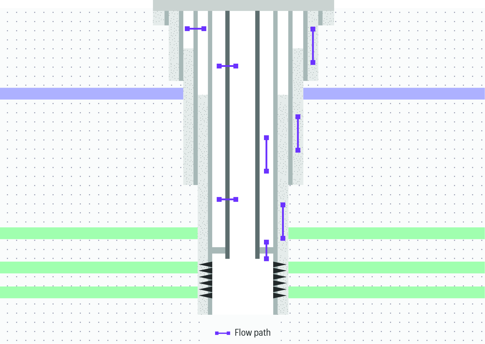
The completion string of a gas producer was upsized from 3 ½’’ x 4 ½’’ to 4 ½’’ x 5 ½’’ with 13% chrome tubing to enhance production. Prior to starting the workover, the A-annulus was successfully pressure tested to 1,500psi. The old completion string was cut above the AHC packer, retrieved and replaced with the new ‘13CR95’ tubing together with a new packer. An A-annulus leak was then observed after setting the packer, but with no TCA communication.


Before continuing, the operator needed to understand the integrity dynamics at play and ensure that the new packer was sealing. Conventional diagnostics could have meant another costly workover, lost production, and the risk of damage to the expensive 13CR95 tubing joints. All of which were clearly undesirable.

Multi-Seal-Integrity-well-sketch
Multi Seal evaluates the seal performance of multiple barriers, locating leaks and flowpaths throughout the well system, from the wellbore to the outer annuli.

Solution

To identify the integrity breach, TGT designed a diagnostic programme utilising the ‘True Integrity’ system with Chorus (acoustic) and Indigo technology. Slickline conveyance was used for efficient and low cost rigless operation, and minimal footprint.


Two survey passes were deployed, one with the well shut-in and another with continuous water injection into the A-annulus. During shut-in conditions, the baseline temperature and acoustic responses confirmed that there was no cross flow or lateral flow anywhere in the well system.


Injection was then started in A-annulus and the acoustic and temperature surveys were repeated. This time, the temperature profile exhibited a cooling effect caused by water being forced into A-annulus, but there was no temperature difference across the upper packer.


Notably, clear acoustic responses were evident at two intervals under injection conditions. A high amplitude wide frequency band acoustic signature, typical of ‘leak flow’ was observed at X175 ft. Also, a lower amplitude, lower frequency signal was observed around X650 ft. No acoustic signal was observed across the upper packer confirming it was sealing properly.

CS027 Multi Seal Integrity_LogPlot
Multi Seal Integrity answer product showing comparison between measurements acquired during shut-in and injection conditions. The primary leak point is clearly visible at X175 ft, and a minor leak interval is evident around X650 ft.

Result

The analyst confirmed the leak point in the 9-5/8” casing at X175 ft. The operator was able to assess the integrity of the well and decided not to remediate the casing leak, deciding instead to operate the well with the proper monitoring and risk mitigation plans in place.